How to properly calculate your chain sling
In order to perform safe lifts with your chain slings, you need to know, among other things, how the maximum load is affected by the dimensioning of the tool and the lifting angles. Here we have gathered the information you need to be able to dimension your chain sling correctly.
Load table for chain sling Grade 10
The table specify the maximum load for general chain dimensions in Grade 10 used for chain slings
| 1-leg | 2-leg | 3- and 4-leg | Endless | |||||||
| Safety factor 4:1 |  |
 |
 |
 |
 |
 |
 |
 |
||
| Angle of inclination | Straight lift | Laced | U-lift | 0°-45° | 45°-60° | 0°-45° | 45°-60° | Straight lift | Laced | U-lift |
| Load factor | 1 | 0,8 | 2 | 1,4 | 1 | 2,1 | 1,5 | 2 | 1,6 | 4 |
| Dia. (mm) | WLL ton | |||||||||
| 5 | 1 | 0,8 | 2 | 1,4 | 1 | 2 | 1,5 | 2 | 1,6 | 4 |
| 6 | 1,4 | 1,12 | 2,8 | 2 | 1,4 | 3 | 2,12 | 2,8 | 2,24 | 5,6 |
| 7 | 1,9 | 1,5 | 3,8 | 2,65 | 1,9 | 4 | 2,8 | 3,8 | 3 | 7,6 |
| 8 | 2,5 | 2 | 5 | 3,55 | 2,5 | 5,3 | 3,75 | 5 | 4 | 10 |
| 10 | 4 | 3,15 | 8 | 5,6 | 4 | 8,4 | 6 | 8 | 6,3 | 16 |
| 13 | 6,7 | 5,3 | 13,4 | 9,5 | 6,7 | 14 | 10 | 13,4 | 10,6 | 26,8 |
| 16 | 10 | 8 | 20 | 14 | 10 | 21,2 | 15 | 20 | 16 | 40 |
| 19 | 14 | 11,2 | 28 | 20 | 14 | 30 | 21,2 | 28 | 22,4 | 56 |
| 20 | 16 | 12,8 | 32 | 22,4 | 16 | 33,6 | 24 | 32 | 25,6 | 64 |
| 22 | 19 | 15 | 38 | 26,5 | 19 | 40 | 28 | 38 | 30 | 76 |
| 26 | 26,5 | 21,2 | 53 | 37,5 | 26,5 | 56 | 40 | 53 | 42,4 | 106 |
| 32 | 40 | 31,5 | 80 | 56 | 40 | 85 | 60 | 80 | 64 | 160 |
* When multi-leg chain slings are used in laced lift reduce value with 20%.
** In asymmetrical lifting, the lifting capacity is reduced. Contact CERTEX Danmark A/S for advice
Calculation of working load limit (WLL) for chain slings
When the exact information about weight, lifting angle and position of the centre of gravity is known, you can calculate the working load limit using the trigonometric method as follows:
2-leg sling
WLL (ton) = 2 x WLL for single leg sling x cos β
3- and 4-leg sling
WLL (ton) = 3 x WLL for single leg sling x cos β
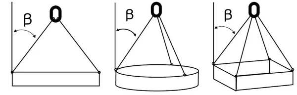
Note: If the load is uniformly on all 4 legs in a sling the following formula can be used in exceptional cases:
WLL (ton) = 4 x WLL for single leg sling x cos β
β = the legs angle against the vertical surface.
In case of a multi-leg sling, the maximum load of the master link must be at least equal to that of the sling. In the case of 3- and 4-leg slings, the maximum load of the transition link of the top link must be at least 1.6 times the maximum load of the chain in question.
In case of alternative dimensioning, the sling can be marked with the calculated maximum load for the angle in question.
WARNING! If the sling is to be used for a projected lift with a smaller lift angle (β) than 45° and thus a higher maximum load than the normal rated load, this must be communicated when ordering the sling.
Sharp edges
Edge protectors should be used to prevent sharp edges from damaging the lifting equipment. As a rule, the radius (R) of the edge should be > 2 x the chain diameter. When lifting with chain directly on lugs it is recommended that lug diameter greater than 3 x the pitch of the chain should be used. If a lug diameter is less than this, the WLL must be reduced by 50%.
| Edge R | R > 2 x chain Ø | R > than chain Ø | R < than chain Ø |
| Load factor | 1 | 0,7 | 0,5 |
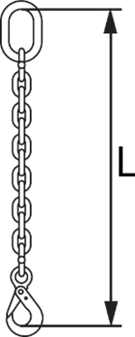
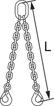
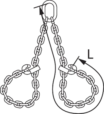
Tolerance of length
The length (L) shall be measured between the “bearing points” or the perimeter for endless slings.
The length on each leg shall be nominal length with a tolerance of -2/+2 chain link lengths.
The difference in length (usually the same for all legs) between the shortest and longest leg in a multi-leg sling, assembled with connecting links, shall not exceed 10 mm if the sling is 2 m or longer slings 5 mm/m is current.