In the MRT terminology there are two well-known acronyms LF and LMA, both claimed by two main standards the ISO4309 and the EN12927:
- LF stands for Localized Fault. Sometimes it can also be found as LD, Localized Defect.
- LMA stands for Loss of Metallic Area. These two signals usually represent the workhorse of each MRT manufacturer.
In this article, you will learn how to distinguish them, learning how they are created, their physical meaning and the conditions in which they work best.
The Localized Fault signal
The LF technology is the most ancient of MRT systems. This well-known signal measures the leakage magnetic flux, in presence of a defect on a magnetized object, such as a steel wire rope.
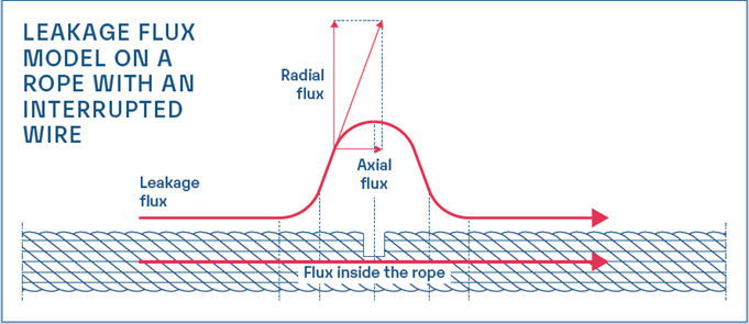
As it shown by the picture above, when there is a defect on a rope fully saturated, part of the magnetic field comes out from the rope, crossing the defect. This phenomenon occurs due to a gap in the rope introduced by the defect. The flux lines variates, meeting a zone (the gap) with a different magnetic reluctance. This variation will occur in the air surrounding the rope. The relative intensity and direction will depend on the entity and shape of the defect. Probes placed in a strategic position of the device will detect the flux, convert it in a voltage, finally extracting the signal.
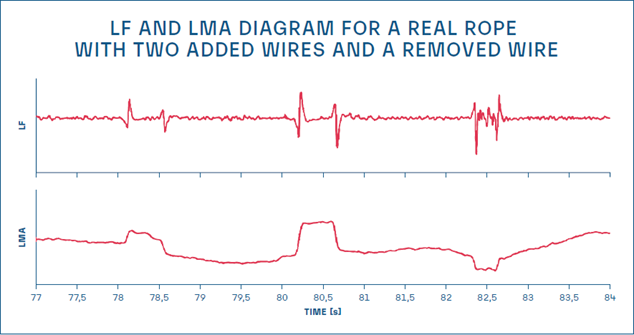
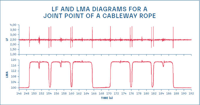
In the following pictures it is possible to observe two examples of typical signals obtained with the LF technology.


Broken wires and corrosion can be both detected by the LF technology. It is important to remark that each signal must be interpreted by a trained technician. In the graphs there are not a real indication about the number of broken wires, the entity of the corrosion or the loss of metallic area, neither a percentage value on the axis. These results are moved on the interpretation side. A trained technician reading the diagrams can easily evaluate the rope real condition. The strong stability, the simple linearity and the reliability (no strange end effects or signal oscillations) characterize the LF signal. For this reason, the LF signal is the only signal claimed by the EN12927 test certification procedure. Without passing this test, it is not possible to operate in the cableway sector.
Loss of metallic area
The LMA has been developed to provide the user a damage quantification, knowing “how much” defects (usually corrosion) affects the rope metallic section. The diagram associated to this signal is mainly given in percentage. The technician will read on the diagram a value (-2%, -5%, etc.), corresponding to the loss of the metallic section in a well-defined point.
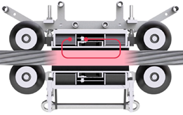
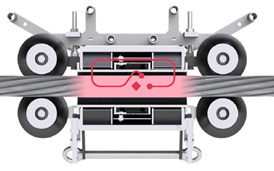
1. The relation between the volume and the section of a rope
The real name of the LMA should be LMV (Loss of Metallic Volume). When there is a defect in a rope, there is a variation in the total magnetic reluctance. The rope can be seen as an electric resistance, its value will depend on its physical characteristics. The defect area is a zone where the iron has been replaced by air modifying the total value of the resistance. In the magnetic parallelism this phenomenon is called reluctance. The more are broken wires and/or corrosion the higher will be the reluctance, because there will be more obstacle the flow of the magnetic flux. The blue circle in Picture 3 represents the measuring point in the device for detecting flux variation. It is possible to state that under certain hypothesis, the measured flux is proportional to the volume of defect or the rope.
Which is the relation between the volume and the section of a rope?
- If the length of the defect is higher than the length of the device, the decreasing of the volume is proportional to the decreasing of the section. Only under this hypothesis the LMV coincides with the LMA.
- If the defect is shorter than the length of the device, the signal is littler, as shown in the picture below.
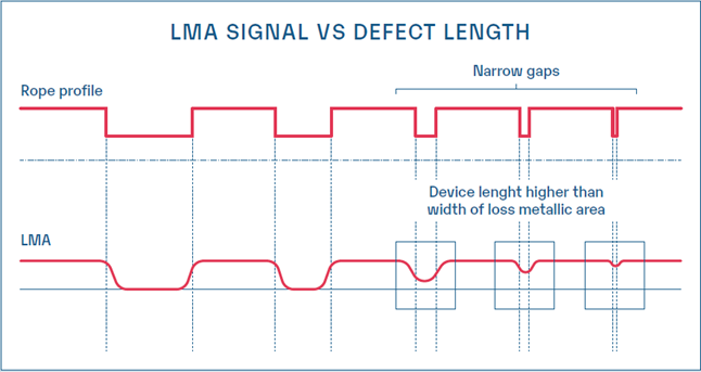
This is the reason why the LMA signal is normally used to identify ‘long’ defects, such as corrosion, wearing and so on. It is not normally suitable for the detection of broken wires.
A typical LMA signal is shown in Picture.5, the rope is in a good condition until 194m, then there is a loss of about 10-15% for 30m.

2. The end effects
The LMA measurement is directly connected to the main flux passing inside the rope and the magnetic circuit. Any modification of the flux path can be read by the probes as a change in the rope section. This is certainly true when the flux changes due a real defect on a rope, but sometimes the magnetic field path can be distorted by some external phenomena. A clear and frequent example is the “end effects phenomenon”, which appears few meters before the rope termination. Imagine performing a test on a cableway, where the rope is a closed loop. In this case, the quantity of rope that there is on the front of the device is the same on its back. In other words, the external magnetic configuration is the same, as well the flux lines. If we perform the test on a crane, at a certain point the termination of the rope will get closer to the device and the quantity of metallic rope on the back and on the front of the system will be different. This fact will create a distortion of the flux lines that will modify the main field in the measurement point and consequently the signal.
The next picture shows an example of this phenomenon. Here the device has been manually moved on a rope, starting from the beginning (1 meter of rope on the back and 10 meters on the front) to the end (the opposite condition). As you can see the average level of the chart moves from one value to another, giving a false indication of a change in terms of section. To sum up, in this laboratory tests where defects have been created artificially close to the rope termination, it is almost impossible to read the real changes in the cross section. Why should be easier on a field inspection?

3. Sensitive to the external environment
The LMA signal is much more sensitive to the external environment than LF. If during the test some metallic parts will move close to the system, there will be a modification of the magnetic flux lines, affecting probably the inspection result. This is one of the reasons why the device must be positioned in a free environment.
Finally, we need to remember that the LMA diagram is usually highly filtered, that will strongly by software procedures, that modifies the appearance of the diagram itself. The main advantage is a better trace provide better interpretation, but the final user should maintain the control of all the process. When closed algorithms are applied and the customer has no control on them, a dangerous situation might emerge. This is the classic situation where the user is operating well but the starting point is completely wrong, consequently the inspection.
LF of LMA
- LF is technically recognized as the most stable signal and is the only defect completely regulated (EN12927). In this signal defects and amplitude are not directly correlated and can vary from a defect to another, depending also on the shape of the damage. For this reason, the analysis requires the interpretation of the user. Under a proper training, technicians will be able to correctly read the diagrams providing to their customers the rope status certificate.
- LMA is a false easy signal. This is its main disadvantage. Unfortunately reading ‘-5%’ is not enough to define the real rope status. This is a huge risk because also people without a deep signal knowledge of the phenomenon can read it. From our experience, if there is a good training around the LMA theory this could be a good “supporting signal” of the LF one. If customers are not correctly trained, they should avoid the LMA signal. Consider also that there are some devices in which the ‘dual signal’ (LF+LMA) is not obtained by using two different probes, but with a mathematical computation. In other words, sometimes, the LF diagram that you see on the screen is only the numerical derivative of the LMA signal. This is physically wrong and any false signal that you can have on the LMA will be moved also on the LF. In other words, if a system is equipped with the LMA, the customer should check that also the LF is available and that the LF is obtained by a separate probe circuit.
More about Magnetic Rope Testing?
Discover our articles about Magnetic Rope Testing (MRT):
- When is an MRT suggested?
- Rope inspection, safety and the ISO4309 regulation
- The EN12927, is your MRT device in compliance with the standard?
- MRT-training
- A permanent MRT system
- The magnetization curve of a steel wire rope
- How is MRT equipment made
- How to choose an MRT device
- How to develop customized magneto-inductive equipment


